Semiconductors
The basis for the construction of diodes and transistors
Table of Contents
A semiconductor is a material whose electrical conductivity is between the conductors and insulators. Their resistance and conductivity depends on temperature and admixtures. [W] The most commercially used semiconductors are those based on silicon, and in the past also on germanium. In addition to these two elements (in crystalline form), a whole spectrum of other substances from groups 13-15 is used, which can form two, three or four-element compounds.
P-n junction
The basic element of a semiconductor system
[003] Additions of atoms of other elements are used to obtain the increased conductivity of the semiconductors. For example, arsenic or antimony causes the appearance of free electrons, which are a source of negative charges. These semiconductors are of the n (negative) type. In turn, indium and barium cause a shortage of electrons, because their atoms take electrons from the environment from silicon atoms, causing the formation of positive charges. They are p (positive) semiconductors. N-type and p-type semiconductors, joined together by a special technological process, form an essential part of each semiconductor element, called the p-n layer. At the boundary of these semiconductors, a p-n junction is formed, carrying current from p to n.
Semiconductor diode
Component of the construction of rectifiers and signaling elements
[003] A two-element component (di or two), intended for example for the construction of rectifiers, protections or, in the case of LEDs, also as a signaling or lighting element. It is a p-n junction with a resistance in the forward direction approx. 10,000 times lower than in the reverse direction.
[101] The diodes can be used to recreate the amplitude of the signal, shift the signal by a constant component or multiply the voltage.
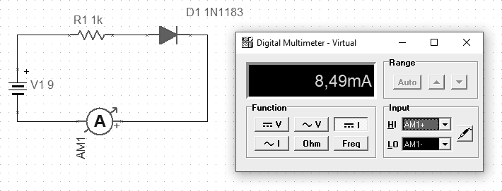
[202] A silicon diode should be connected in the direction of the symbol’s arrow if we want it to conduct current. Setting it in the opposite way is a blockage state in which there should be no conduction up to a certain voltage. If we exceed the parameters of the designed operation of such diodes, then it will be damaged and can conduct current in both directions.
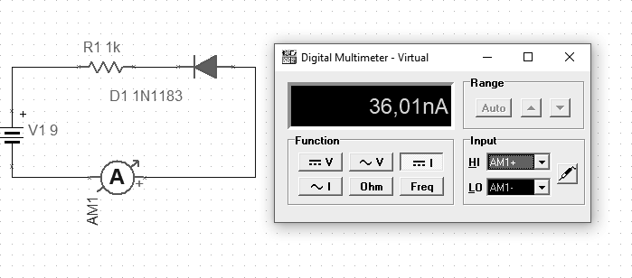
If the diode is connected in the reverse direction, the measured current should be negligible. In the example below, the current is approximately 36 nA.
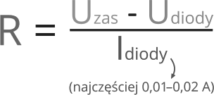
The voltage drop across the diodes (here LED) depends on the substance used, which determines the given color of the luminescence. These drops usually occur from 1.7 to 3.6 V. The diodes have specific operating parameters and when supplying voltage to the system, make sure that the current value is correct, which is limited by a series resistor. The order of connection in the series connection in this case does not matter, so the resistor can be both before and after the diode.
To illustrate that the order of connection of the resistor and diode does not matter, below are two similar examples to illustrate.
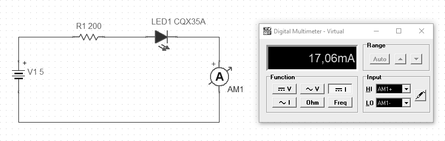
We get the same result in both examples.
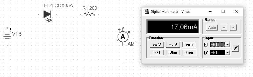
The current can be translated as an analogy of water pressure in a closed system, so the order will not be of particular importance when connecting elements in series.
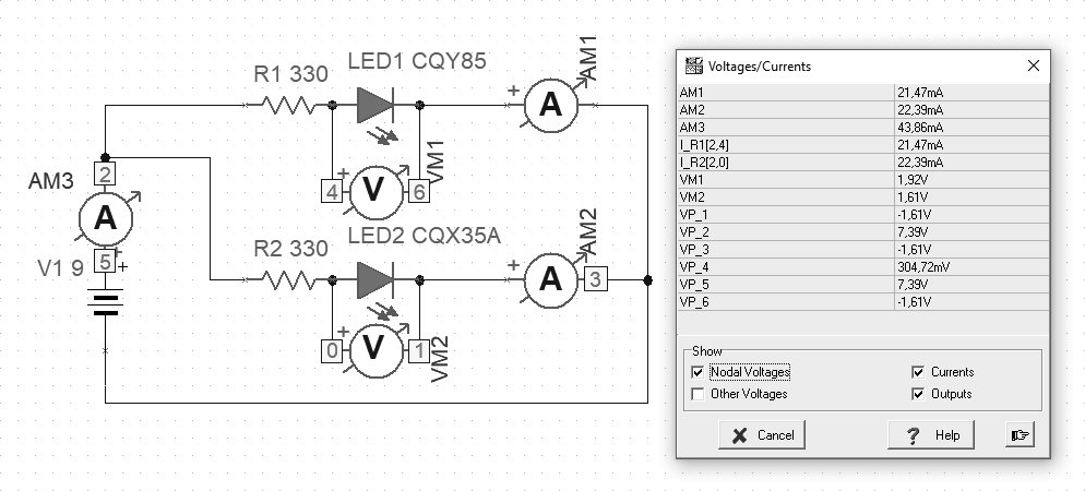
The diodes can be connected in series as above. Important operating parameters are forward voltage, standard and maximum current, and reverse parameters. Knowing these parameters, we can choose the appropriate resistors and arrange the whole into a circuit as above.
“The German physicist Ferdinand Braun, a 24-year-old graduate of the University of Berlin, studied the characterization of electrolytes and conductive crystals at the University of Würzburg. In 1874, while examining galena crystals (lead sulfide) with the tip of a thin metal wire, he noticed that the current was flowing freely in only one direction. Braun discovered the electric straightening effect that occurs where metals meet certain crystalline materials. Braun demonstrated this semiconductor device in Leipzig in 1876, but it did not find any useful application until the advent of radio in the early 1900s.” [207]
Zener diode
Reference voltage source
[101] Zener diodes are most often used as an almost constant voltage reference source. If the input voltage is less than the zener voltage, the diode is non-conductive and will not stabilize the voltage.
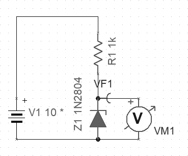
[209] A zener diode is always used as a stabilizer in reverse biased conditions. A Zener diode DC voltage regulator circuit can be designed to provide a constant voltage across the load regardless of changes in input voltage or load current.
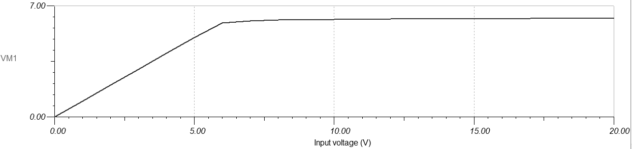
As you can see in the above diagram, the value of the breakdown voltage for the 1N2804 model of the Zener diode is 6.8V, according to the catalog note.
Examples available at https://github.com/michalasobczak/simple_hpc/tree/master/SeriesPartOne