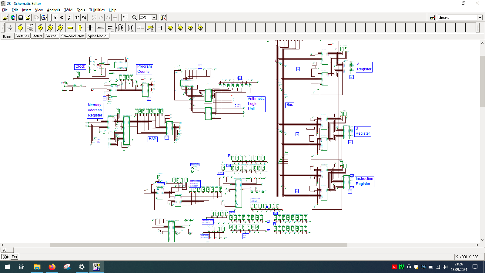
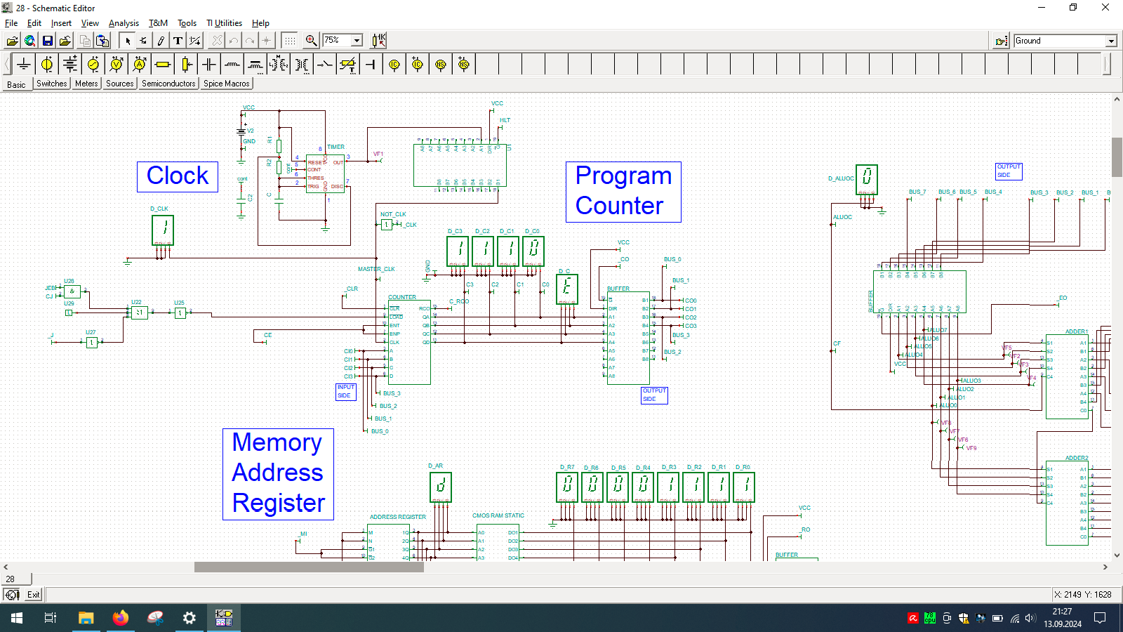
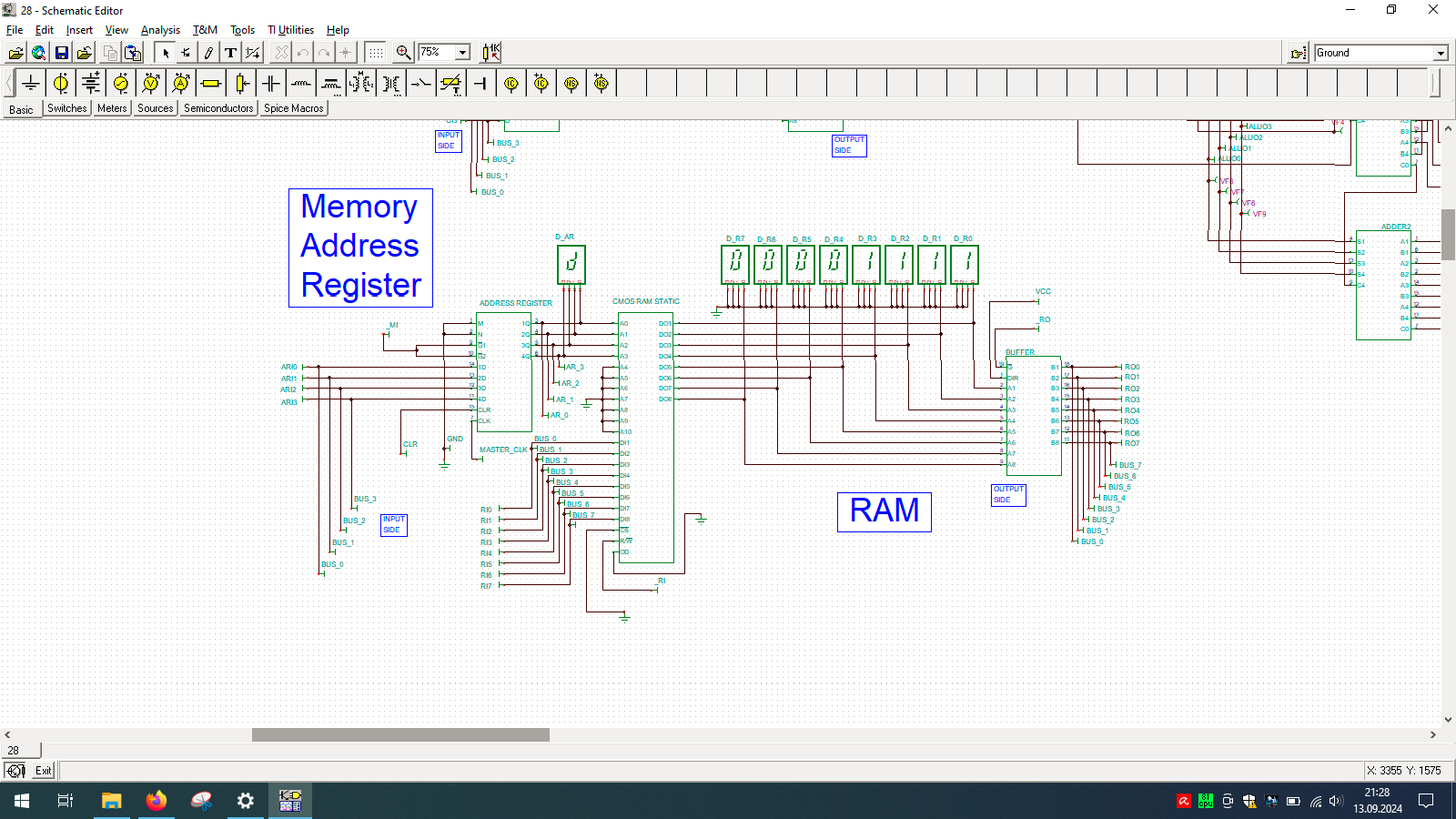
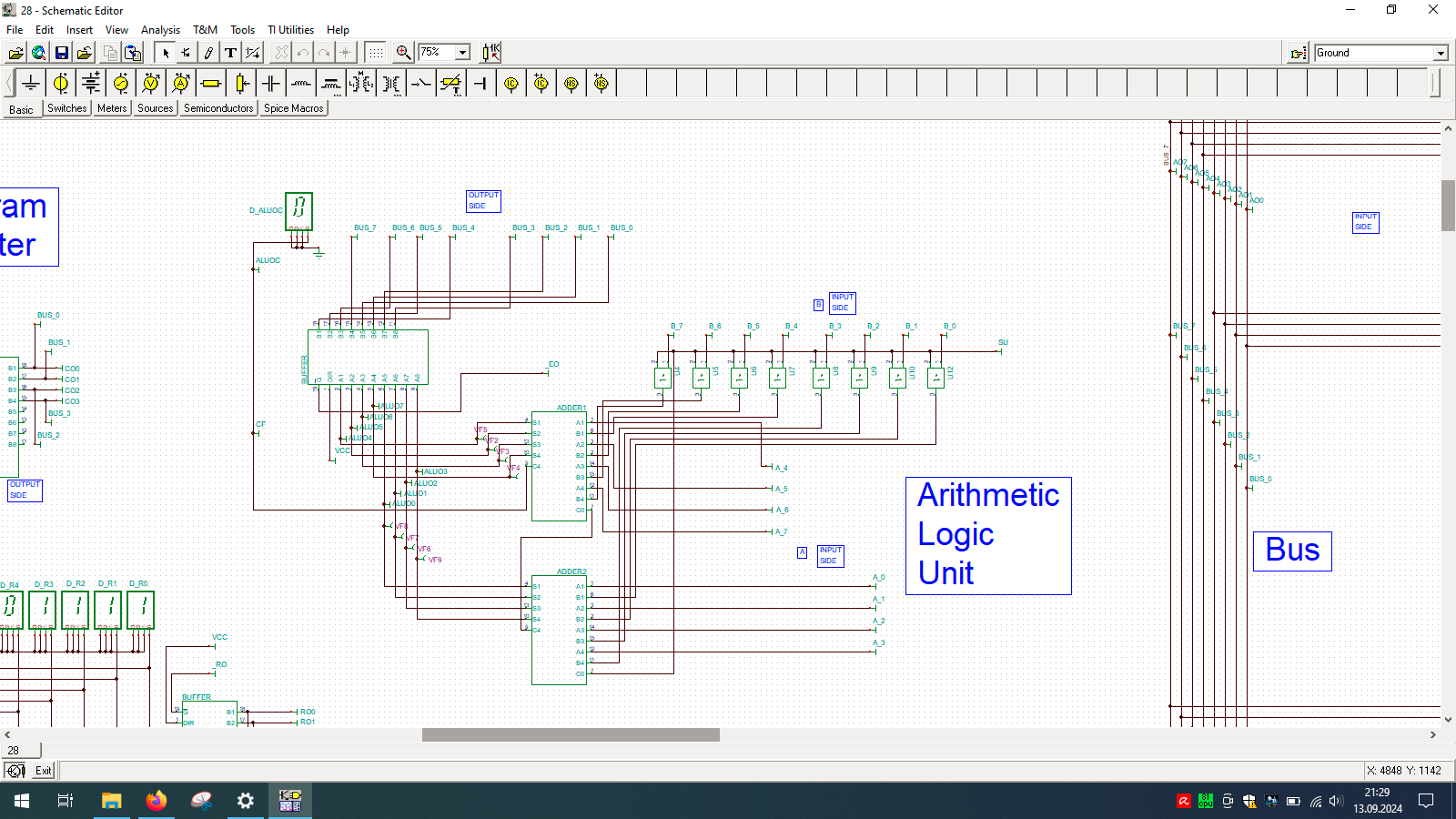
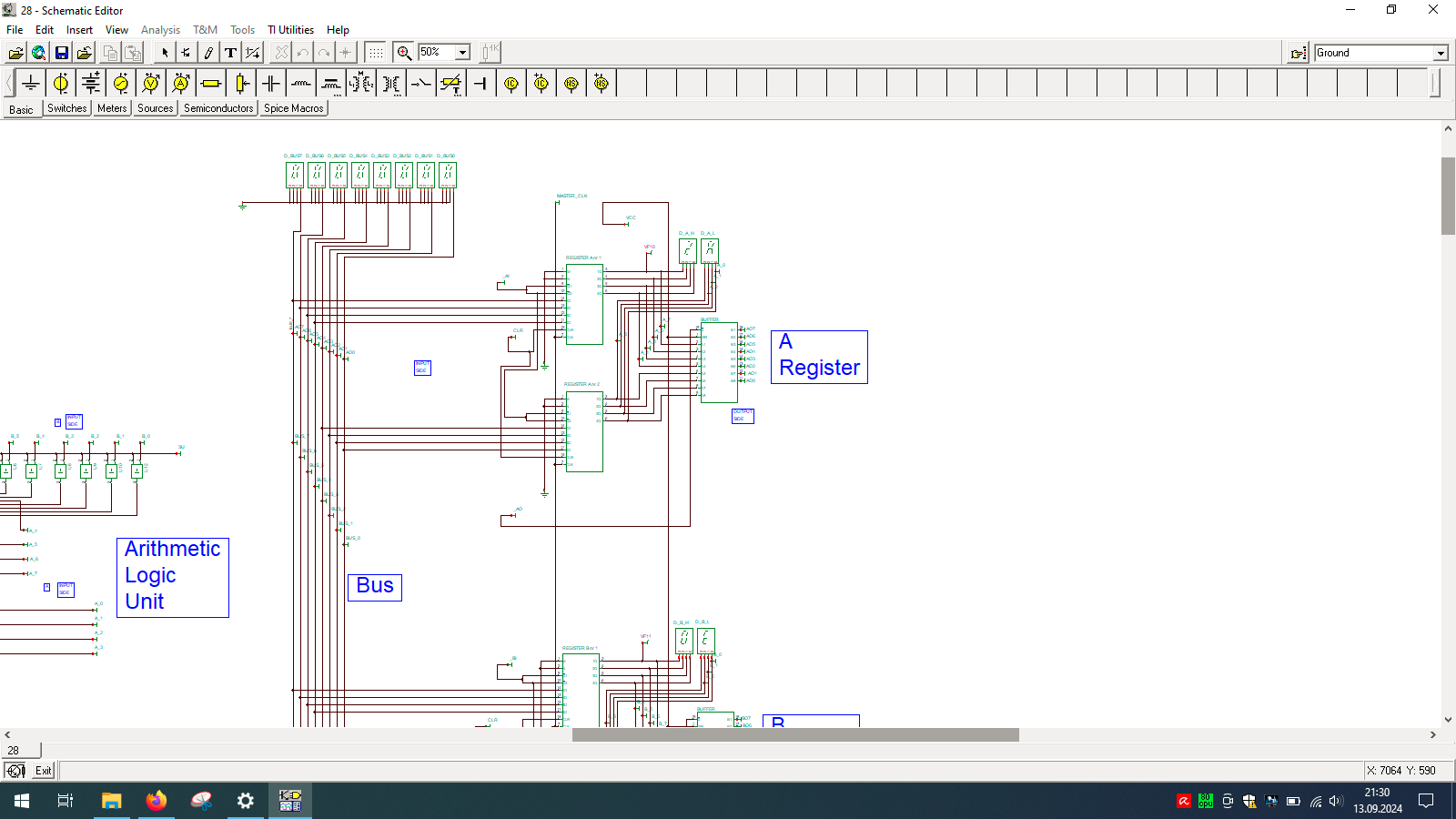
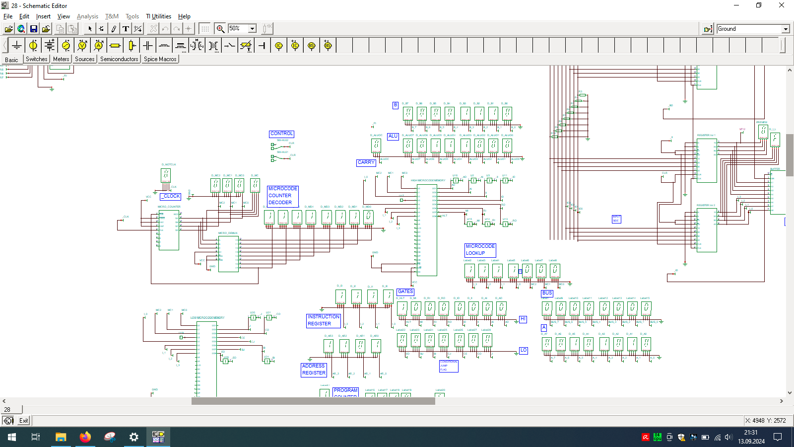
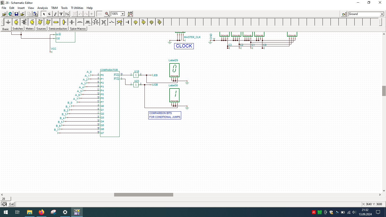
Even wondered how computer is built? And no, I’m not talking about unscrewing your laptop… but exactly how the things happen inside the CPU. If so, then check out TINA from Texas Instruments and open my custom-made all-in-one computer.
I spend few weeks preparing this schematic. It contains clock, program counter, memory address register, RAM, ALU, A&B registers, instruction register, microcode decoder, instruction register, address register and program counter. Well that’s a lot ot stuff you need to build 8-bit data and 4-bit address computer, even in simulator.
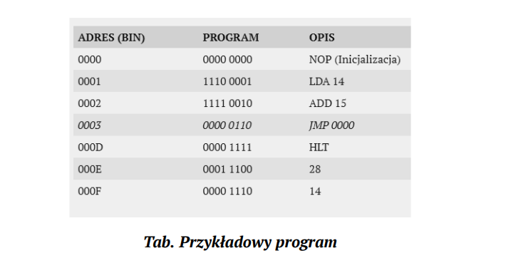
Sample program in my assembly + binary representation, which needs to be manually enter into memory in the simulator as there is input and output device designed for this machine. You need to program directly into memory and read its results also directly from the same memory but in different region.
A semiconductor is a material whose electrical conductivity is between the conductors and insulators. Their resistance and conductivity depends on temperature and admixtures. [W] The most commercially used semiconductors are those based on silicon, and in the past also on germanium. In addition to these two elements (in crystalline form), a whole spectrum of other substances from groups 13-15 is used, which can form two, three or four-element compounds.
P-n junction
The basic element of a semiconductor system
[003] Additions of atoms of other elements are used to obtain the increased conductivity of the semiconductors. For example, arsenic or antimony causes the appearance of free electrons, which are a source of negative charges. These semiconductors are of the n (negative) type. In turn, indium and barium cause a shortage of electrons, because their atoms take electrons from the environment from silicon atoms, causing the formation of positive charges. They are p (positive) semiconductors. N-type and p-type semiconductors, joined together by a special technological process, form an essential part of each semiconductor element, called the p-n layer. At the boundary of these semiconductors, a p-n junction is formed, carrying current from p to n.
Semiconductor diode
Component of the construction of rectifiers and signaling elements
[003] A two-element component (di or two), intended for example for the construction of rectifiers, protections or, in the case of LEDs, also as a signaling or lighting element. It is a p-n junction with a resistance in the forward direction approx. 10,000 times lower than in the reverse direction.
[101] The diodes can be used to recreate the amplitude of the signal, shift the signal by a constant component or multiply the voltage.
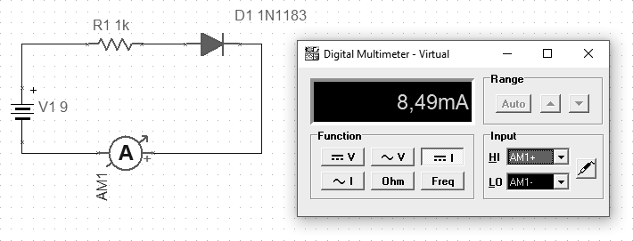
[202] A silicon diode should be connected in the direction of the symbol’s arrow if we want it to conduct current. Setting it in the opposite way is a blockage state in which there should be no conduction up to a certain voltage. If we exceed the parameters of the designed operation of such diodes, then it will be damaged and can conduct current in both directions.
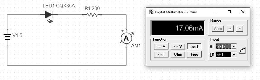
Fig. LED in forward direction (p09)
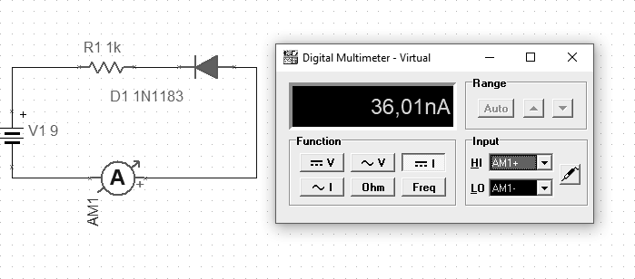
If the diode is connected in the reverse direction, the measured current should be negligible. In the example below, the current is approximately 36 nA.
Fig. LED connected in blocking (p10)
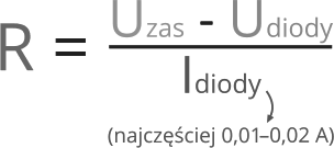
The voltage drop across the diodes (here LED) depends on the substance used, which determines the given color of the luminescence. These drops usually occur from 1.7 to 3.6 V. The diodes have specific operating parameters and when supplying voltage to the system, make sure that the current value is correct, which is limited by a series resistor. The order of connection in the series connection in this case does not matter, so the resistor can be both before and after the diode.
Eq. The required resistance of the resistor to power the diode
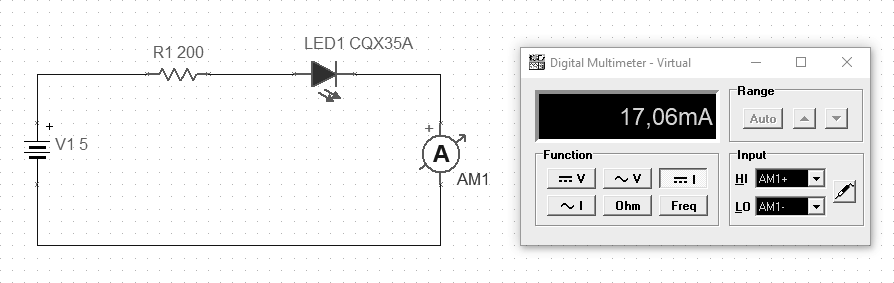
To illustrate that the order of connection of the resistor and diode does not matter, below are two similar examples to illustrate.
Fig. Resistor “before” the diode (p11)
We get the same result in both examples.
Fig. Resistor “after” the diode (p12)
The current can be translated as an analogy of water pressure in a closed system, so the order will not be of particular importance when connecting elements in series.
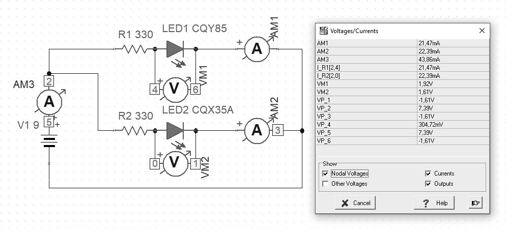
Fig. Parallel connection of series diode + resistor (p13)
The diodes can be connected in series as above. Important operating parameters are forward voltage, standard and maximum current, and reverse parameters. Knowing these parameters, we can choose the appropriate resistors and arrange the whole into a circuit as above.
“The German physicist Ferdinand Braun, a 24-year-old graduate of the University of Berlin, studied the characterization of electrolytes and conductive crystals at the University of Würzburg. In 1874, while examining galena crystals (lead sulfide) with the tip of a thin metal wire, he noticed that the current was flowing freely in only one direction. Braun discovered the electric straightening effect that occurs where metals meet certain crystalline materials. Braun demonstrated this semiconductor device in Leipzig in 1876, but it did not find any useful application until the advent of radio in the early 1900s.” [207]
Zener diode
Reference voltage source
[101] Zener diodes are most often used as an almost constant voltage reference source. If the input voltage is less than the zener voltage, the diode is non-conductive and will not stabilize the voltage.
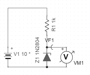
Fig. The zener diode is connected to the block (p14)
[209] A zener diode is always used as a stabilizer in reverse biased conditions. A Zener diode DC voltage regulator circuit can be designed to provide a constant voltage across the load regardless of changes in input voltage or load current.
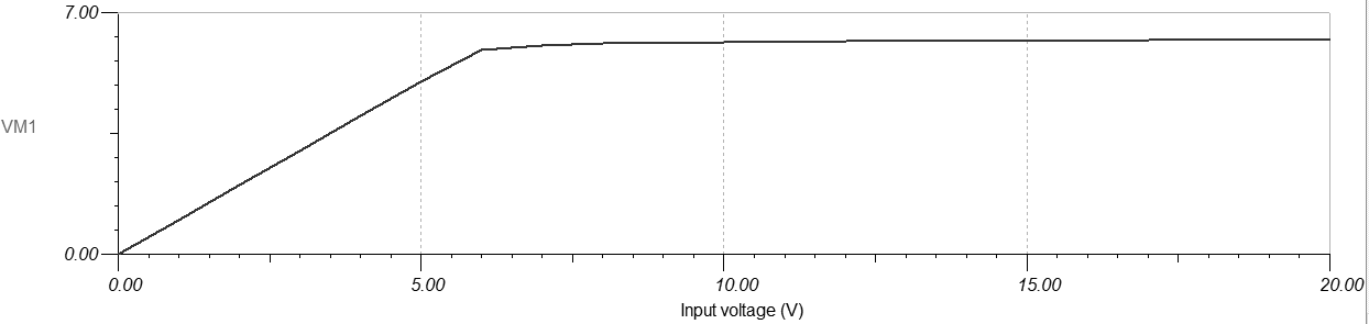
Fig. Measurement of the breakdown voltage
As you can see in the above diagram, the value of the breakdown voltage for the 1N2804 model of the Zener diode is 6.8V, according to the catalog note.
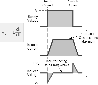
[209] Just as a capacitor works by storing energy as an electric field, an inductor stores energy as a magnetic field. The energy stored in the coil is calculated in terms of current. The capacitor acts as an insulator of the circuit while the inductor acts as its conductor. The coils have inductance expressed in henry [H]. The coils are plugged into the circuit in series with the powered device. The coils are characterized by a maximum current, as their windings have a certain resistance, therefore the flow of current causes a voltage to accumulate on them, which gives the power released by them. Adjusting the operating parameters is to avoid overheating of the coil.
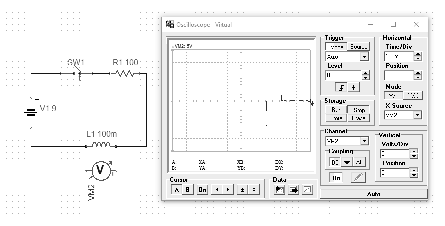
Fig. Difference between continuous power supply and periodic power supply (p08)
The above example (with a cyclic trigger) illustrates the property of the coil of the occurrence of a reverse electromotive force. If we apply voltage constantly, the coil will behave like a piece of wire. However, if there are changes in the intensity of the current flowing through the coil, then we can observe the signal jumps on the measurement.
Fig. Voltage and current in a coil [209]
“The use of electric transformers and inductors in the electrical sphere is such a common practice that it is difficult to imagine a world without these devices. When the property of inductance was discovered in the 1830s by Joseph Henry and Michael Faraday (separately and on different continents), the technology was revolutionized. Inductance was first discovered by Faraday in a simple but strange way: he wrapped a paper cylinder in wire, fastened the ends of the wire to a galvanometer (an electric current measuring device), and moved the magnet to and from the cylinder. The galvanometer reacted by revealing that it was producing a tiny current. ” [201]
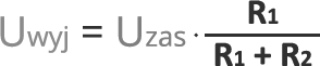
[202] The next example I want to present in practice is a popular voltage divider. It allows the output voltage to be reduced to the desired value due to the properties described a little earlier.
Eq. The output voltage at the divider
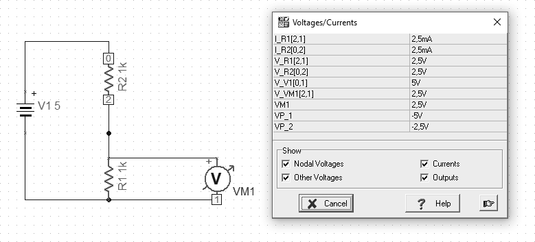
Bearing in mind the above formula, we can assume that we want to reduce the input voltage of 5V to the expected 2.5V at the output. So we use two 1K resistors connected in series.
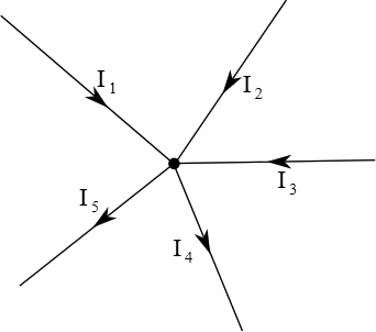
[W] One of the basic principles of current flow is the first law of Kirchhoff, which says that for the electric circuit node, the algebraic sum of flow rates is zero. The sum of currents flowing into the node is equal to the sum of currents flowing out of this node. This law results from the principle of keeping the load.
Fig. Kirchhoff’s first law
Kirchhoff’s second law says that the sum of voltage drops in a closed circuit is zero, assuming that the voltage drop is its negative increase.
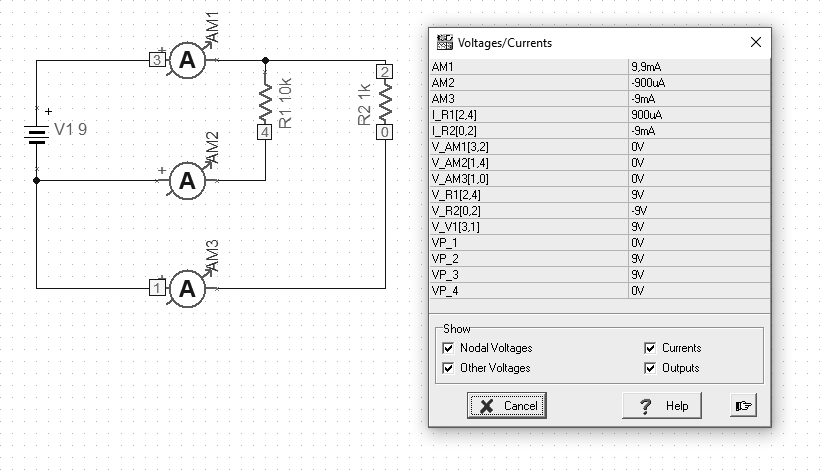
[202] For the purposes of illustrating the law of Kirchhoff, I prepared a simple example below. We start with an example about the first law. 2 resistors are connected, 10k and 1k respectively. We attach 3 ammeters in turn. Sum currents from the circuits of subsequent resistors give the current value for the entire circuit. We can measure this current at a point where there is 1 entrance and 2 outputs.
Fig. Kirchhoff’s first law (P04)
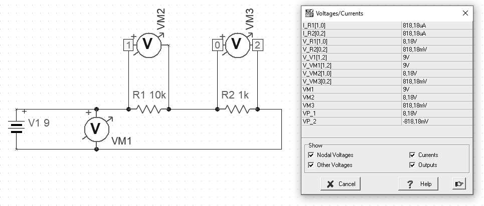
Another example is illustrated by Kirchhoff’s second law. An example shows the difference in the way the circuit elements are connected. By connecting the same voltage values in parallel. By connecting the sum of voltage drops on individual elements, connecting to individual elements.
Fig. Second Law Kirchhoff (P05)
“Gustav Robert Kirchhoff (born March 12, 1824 in Königsberg, died October 17, 1887 in Berlin) – a German physicist, creator of thermal radiation law regarding the relationship between emission and absorption capacity, and rights regarding electrical circuits (first and second law of Kirchhoff)” [W]
[202] Capacitors are divided into polarized and non-polarized depending on whether the direction of their inclusion in the circuit is important. Generally speaking, capacitors filter the waveform of the power source. It is assumed that the longer lead from the capacitor is the positive pole, which is sometimes reflected in the marking in the diagram. Electrolytic capacitors consist of a metal cover and an electrolyte lined with paper. Non-polar (non-polarized) capacitors can be made of ceramic elements or foil. There are also tantalum capacitors which both offer high capacitance and relatively low losses. The physical size of a capacitor depends not only on its capacity but also on its maximum operating voltage.
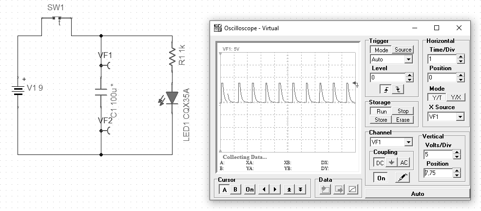
Fig. Capacitor in use with timer and LED (p07)
In the above example, we put a timer switch into the circuit, which in a 1 second cycle turns on for 100ms, causing the capacitor to charge. After the time specified by the parameters of the elements, the LED starts to emit light. When the switch disconnects charging, the capacitor discharges. The time of diode activation is controlled by determining the capacitance of the used capacitor.
However, the main task for capacitors is to filter the power supply. This treatment is used to protect sensitive components, e.g. a microcontroller in a digital circuit. It is most effective to use different types to filter the specific interference. Capacitors are connected to the circuit in parallel.
“A capacitor is a device for the temporary storage of electric charge. What is believed to be the first capacitor was called the Leyden jar, which was invented by Pieter van Musschenbroek in 1746 at Leyden (or Leiden) University in the Netherlands. It was a glass jar wrapped inside and out with a thin metal foil. The outer foil was bonded with the ground, and the inner foil was connected to an electricity source, such as like an electrostatic generator. Though at that time, it was not understood how it worked, experimenters found that the Leiden jar seemed to store an electric charge even when unplugged from the generator. ” [206]
[204] This is the SI unit of resistance. 1 ohm is the electrical resistance between two points on a conductor when a constant potential difference of one volt between the two points causes a current of one ampere in the conductor.
Eq. Unit of resistance
Most, if not all, components have internal resistance, such as batteries. It is not a property that is easily measurable. Circuits intended to show some principles assume that, for example, the power source is an ideal cell and any internal resistances are compensated by additional components of such a circuit, assuming a certain margin of error.
Feeding a resistor with too low resistance in a single-element system causes de facto short-circuit of the contacts of the power source, e.g. a battery, which will probably lead to its degradation. The larger the cross-section of the conductor, the lower its resistance and the larger the surface capable of dissipating heat – hence the conductor can withstand a higher current intensity.
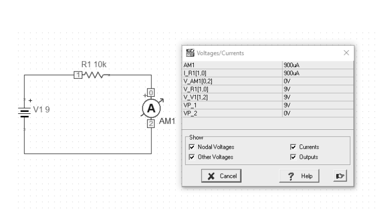
[202] The intensity of the current through a conductor is directly proportional to the voltage applied between its ends. If the resistance is kept constant, then increasing the voltage will increase the amperage. At constant voltage, increasing the resistance reduces the amperage.
[202] Assuming that the battery has a voltage of 9V as the source of electrical energy and the resistor shows a resistance of 10k Ω, then the ammeter, which is connected in series to the circuit, will give a result of about 900mA. This result should also include the internal resistance of the ammeter and the actual battery voltage. The resistance of the circuit itself should also be taken into account. The result of 0.9A will therefore only be an approximation.
Fig. An example of a circuit with a battery, resistor and ammeter (p01)
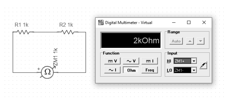
The next example will show how we measure the resistance of series-connected resistors. It is simply their sum.
Fig. Sum of series resistance values (p02)
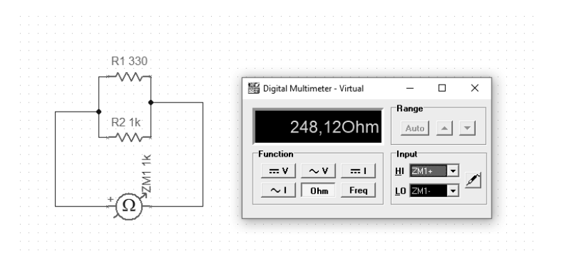
For comparison, we can connect the resistors in parallel. Here, the calculation of the output value of the resistance is slightly different and is described by the formula:
Eq. Parallel resistanceFig. Connecting resistors in parallel (p03)
With this connection, the effective resistance will be less than the smallest component in such a parallel configuration.
“[Georg Simon Ohm] He formulated (1827) a law describing the relationship between the intensity of an electric current and electric voltage, known today as Ohm’s law. He investigated the heating of conductors with the flow of electric current. He found the dependence of resistance from the geometric form of the conductor” [W]
Construction and testing of circuits in the TINA TI program
To translate theory into practice, we can use the TINA package from DesignSoft for Texas Instruments. It is a tool for building virtual analog and digital circuits. The basic version provides the minimum necessary set of elements that can be arranged in the form of a circuit. However, the most important function (at least for me) is the ability to run simulations.
Fig. Available circuit elements in the TINA package
All presented examples of simulations are prepared in TINA TI V9 (Schematic Editor), Special Complementary Basic Edition available free of charge. The schema sources are in the repository for this publication, for independent study github.com/michalasobczak/simple_hpc in the folder SeriesPartOne.
Fig. Oscilloscope [W]
[101] For the purpose of studying a system, the concepts of linearity and non-linearity are adopted. A system with at least one nonlinear element will be a nonlinear system. Nonlinearity consists in the inability to describe the current-voltage characteristic of a given element in the form of a straight equation. When describing a mixed system, consisting of both linear and nonlinear elements, the point of intersection of their characteristics will be the working point.
Note: If we do not need to test the circuit, we can use other packages for electronics such as Frizting, LibrePCB or EAGLE.
Electronics is based on physics. The basic concepts here are voltage, current and resistance. We should start with that. The voltage is therefore a measure of the strength of electric charges. The voltage between two points of an electric circuit or electric field is the difference in electrostatic potential between these points. We measure voltage in volts. We use a voltmeter to measure the voltage. We always measure voltage between two points because it is a potential difference.
The voltage can be constant, variable, alternating. Why we use a given form of tension depends on the purpose, losses, efficiency and probably also safety. The difference between volatility and commutation is a question of waveform shape and its distribution along the axis. Voltage and current are inextricably linked concepts. If there is no voltage in the circuit, no current is flowing in it.
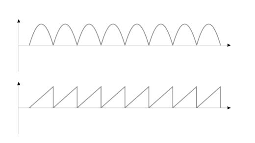
Alternation
Periodic form of a signal with waveforms on both sides of the axis
[204] The current is represented as a shape, the signal can have different forms depending on how it is initiated.
Fig. Alternating waveforms [204]
If we give it a given periodic form, in which its value will alternately take a negative and a positive form, then we will call such a current alternating.
Variability
The periodic form of a signal on one side of the axis
[204] However, if this form is periodic, but not commutative, then we can only speak of a periodic but a variable current. Such a signal is repeatable, but its amplitude waveform does not exceed the axis on the graph. The difference between a constant, alternating and alternating signal is important from the point of view of circuit design.
Fig. Variable waveforms [204]
If a given form of a signal, be it a variable or an alternating one, should have a specific form, the task of various components and systems is to provide them with this target form in the simplest possible way.
Peak frequency and voltage
Signal amplitudes and actual voltage
[204] In a house, we have alternating current with specific parameters, such as 230V and 50Hz frequency. This means that in 1 second there are 50 changes (alternations) from the peak value, then as it falls down, the axis is crossed at the zero point (more precisely across the equilibrium level) to reach the opposite value. These changes create an alternating current sinusoid. There may be a voltage in the network with a certain deviation, between 5 and 10%, depending on the characteristics of the supplied voltage and the installation itself that supports it. Therefore, assuming the maximum values, it is about 250V effective voltage. For a perfectly sinusoidal waveform, the peak value of the ac signals will be
Umax = Usk * √2
For a triangular waveform, this would be the first a square root of 2. For a square wave it will be 1. For an average outlet voltage, the peak voltage may be around 350-360V.
Note: Amplitude is the maximum deviation of the signal from the equilibrium level. Voltage amplitude is denoted as Um, and the current as Im. Finishing this topic, it is worth mentioning that the shape of the current waveform is sinusoidal because the generator core works in a circular motion, which is inseparable from the shape of the sinusoid.